by Jeff Liebermann
This is in WebLog format where the most recent postings are at the top of the page. If you wish to follow the construction in chronological order, please read starting at the bottom of the page.
Dec 4, 2010
The replacement LCD display arrived. It's far cheaper and easier to replace the entire LCD display, than to repair the EL backlighting in the original display. A new display is about $10 on eBay, while a replacement EL backlight screen is about $40. Search eBay for "2002 LCD" which means 20 characters by 2 rows. It should be HD44780 compatible and have the connections on the short edge of the board, not the long edge.
The first challenge was discovering that the original display had 14 connections, while the replacement has 16. I eventually read the data sheet, which declared that the added two pins (15,16) were for the LED backlighting. Inspecting the wire color coding, I found some wire colors were duplicated. Not good as this mean that I would need to either label each wire, or move each wire, one at a time, to the new display. I chose the latter.
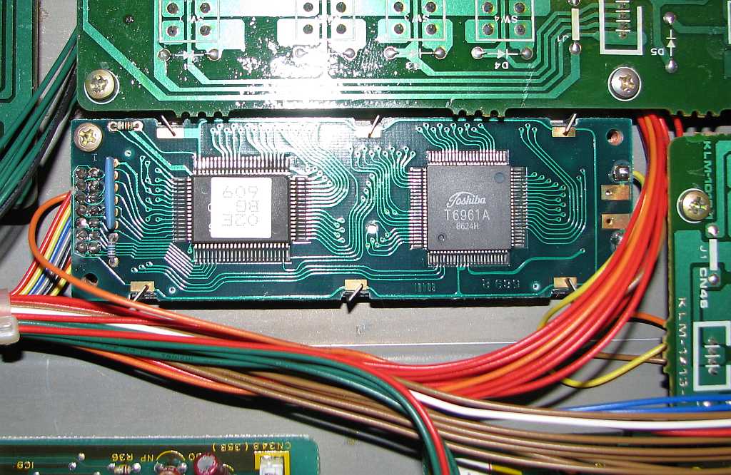
The original LCD (EL backlit) display.
Removing the old display was easy. Two screws and it's out. The second challenge was when I discovered that the original display is 4mm high off the PCB, while the replacement I purchased is 9mm. It fits, but required a nylon space and longer M3-10mm screws and 3/16" nylon spacers. (1/8" spacers would have worked better, but I didn't find any in the junk box).
Once I was sure that it would fit, the third challenge was unsoldering each wire, one at a time, and resoldering it to the new display, without destroying anything. This was greatly facilited by removing a ty-wrap from the cable bundle. The brown and yellow wires, going to the LCD contrast control and the board to the right, were unsoldered, and insulated with tape. These will not be used. However, the orange wire, coming from the same LCD contrast control, goes to Pin 3 of the LCD display. Try really hard not to mix up the wires as I have no easy way to recover. Take photographs as you work so that you can put things back together without guessing. Also, be sure to wipe the display and front panel lens clean before reassembling. I didn't notice the fingerprints until it was back together.
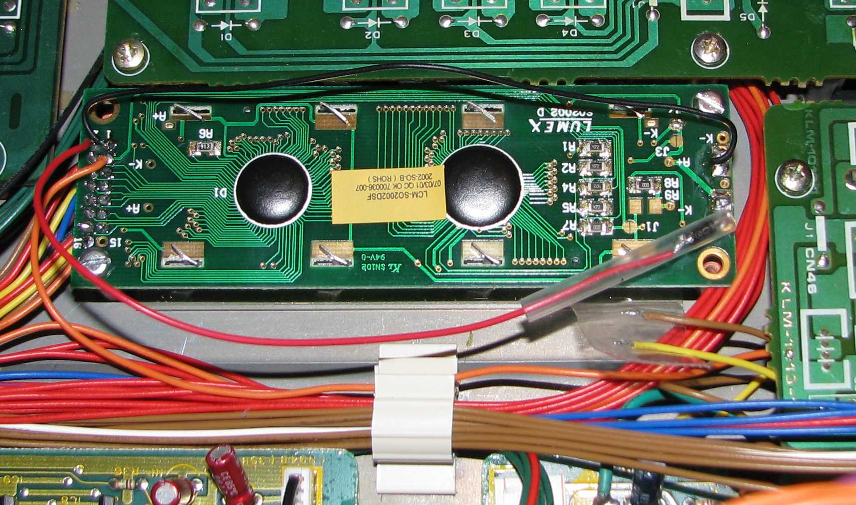
The replacement LCD (LED backlit) display.
Don't worry about backlighting quite yet. Replace the display, apply power, and it should work. You should see the usual displayed characters. Turn the contrast knob and see if that works.
Wiring for LED backlighting is different from EL backlighting. It wants about +5VDC on the LED pins, sorta. If you look at the data sheet, it specifies 4.2VDC as the typical voltage, with 4.6VDC as maximum. Applying 5VDC might kill the LED's. So, I insert a diode in series with the 5VDC and drop the applied voltage to 4.4VDC. Close enough. If you look at the above photo, the K- (cathode) pin is wired to ground at Pin 1 with a black wire. The A+ (anode) pin is wired to +5VDC at Pin 2 through a diode. I used a 1N4007 diode, but almost any power diode will work. Insulate with shrink tube to prevent shorts.
If I had to do all this again, I would probably install an 8x2 0.100 rt-angle pin header and connector for the LCD, for no better reason than to make it easy to try different displays.
Still waiting for the service manual.
Nov 28, 2010
Day 4 and it's cleanup and tweaking time. Most of the time was spent removing spider and bug droppings from the other assorted keyboards. I also spent some time attempting to resurrect a Roland D-5 without much success. I ordered some new 20x2 (2002) LCD displays on eBay instead of trying to fix the backlighting EL panel.
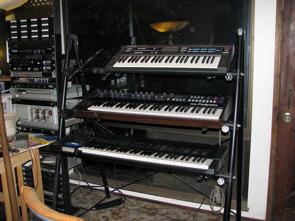
Casio CZ-1000, Korg PolySix, and Korg DSS-1.
Nov 27, 2010
Day 3 and it's time to attack the floppy problem. I drive to my palatial office, and excavate all the likely 3.5" floppy drives out of the recycle pile. I find 5 different mutations of the Teac FD-235HF, which is known to work. Trying them all, none of them work. So much for the easy fix.
Googling for assistance, I find the jumper configuration for the mostly likely to work drive, a Teac FD-235HF-3240. It's for a different instrument, but it does contain the magic formula for disarming automatic density selection (HA) and using it as a 720KB drive. This suggests that most any 1.44MB 3.5" drive will work, but only if it has lots of configuration jumpers.
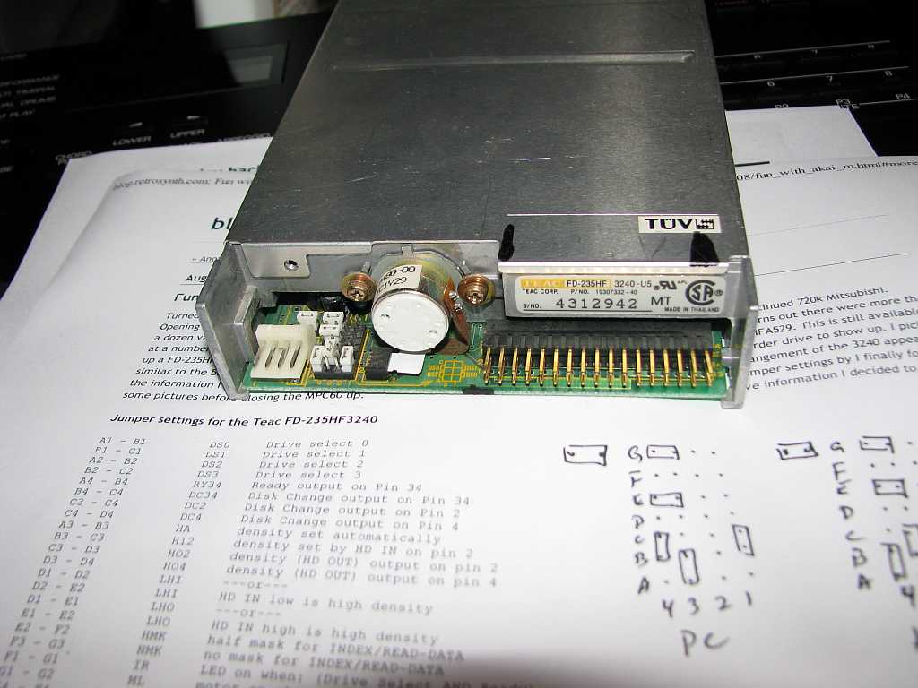
Teac FD-235HF-3240 floppy drive. Jumpers are shown in the correct configuration for the Korg DSS-1.
Nov 26, 2010
Day 2 and it's mostly back together and working. I ordered a service manual on eBay, and expect it to arrive after i'm done. Oh well.
The floppy disk drive is from an ancient Atari 520ST computah. It works, but is too tall to fit in the floppy disk drive bay. It sits on top of the case, upside-down, with the ribbon and power cables dangling out of the front of the DSS-1. Ugly, functional, and will soon be fixed.
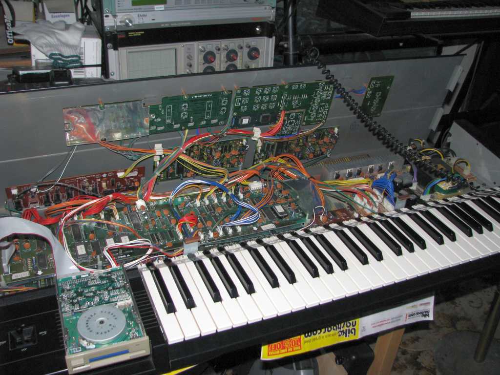
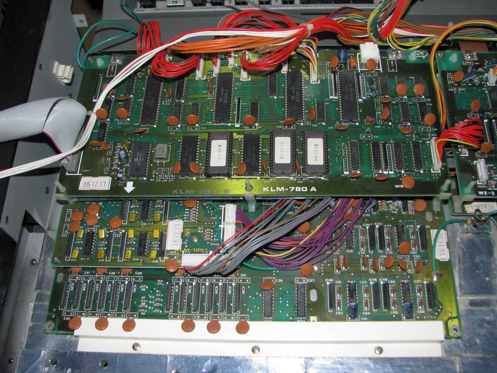
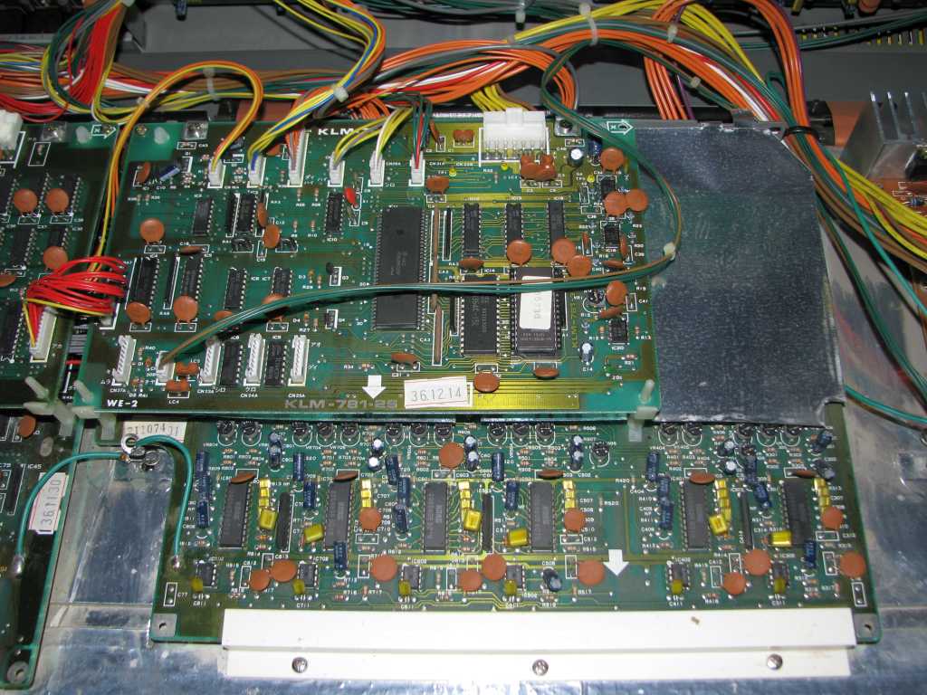
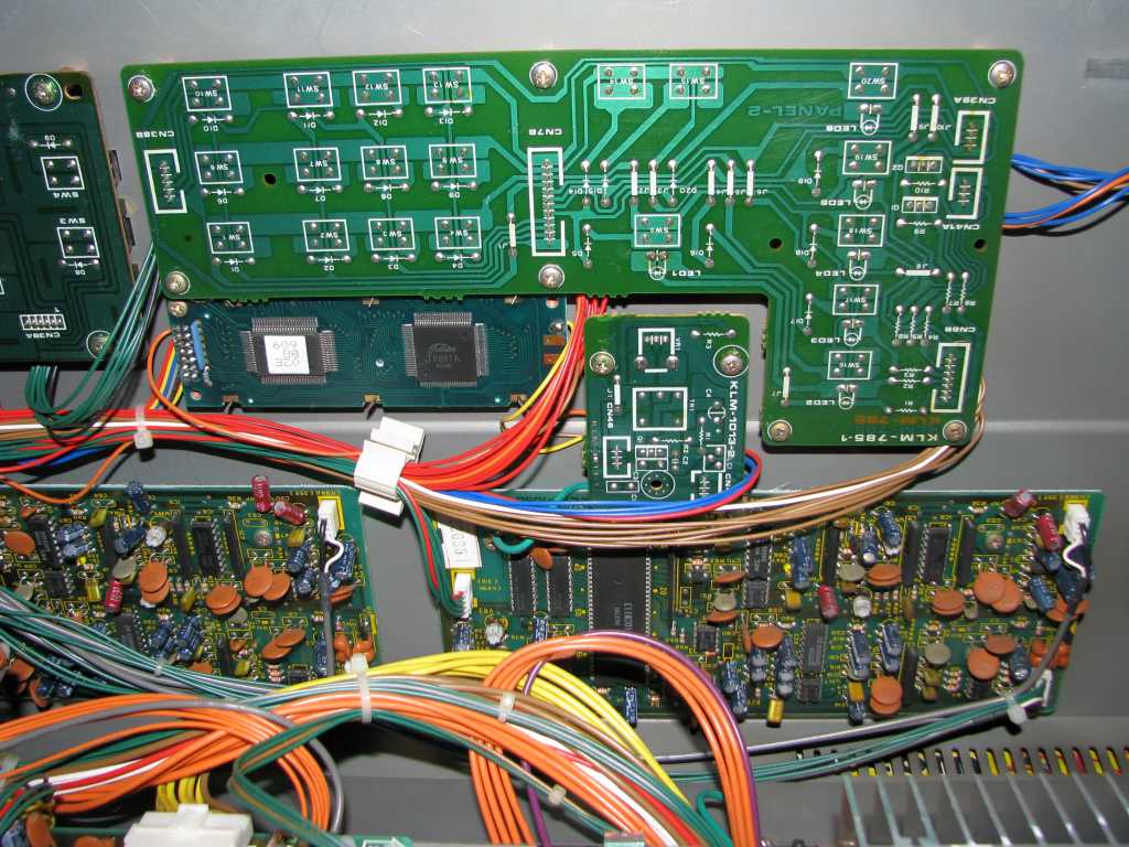
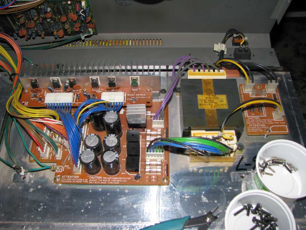
More photos of the guts.
To do: Find replacement screws, fix FD drive, make plastic kbd cover.
Nov 25, 2010
My Korg DSS-1 was giving me enough trouble to justify a general cleanup and rebuild. Opening the case revealed plenty of dust, dirt, water damage, corrosion, rust, dead bugs, jungle rot, stale beer, cola, food debris, staples, paper clips, and some really digusting mold. Not unexpected considering it hasn't been cleaned since I bought it in 1992. During the process of disassembly, I also discovered that some of the screws were missing. Much of the time was spent gaining access to buried boards, and cleaning with 409, a paint brush, and air compressor.
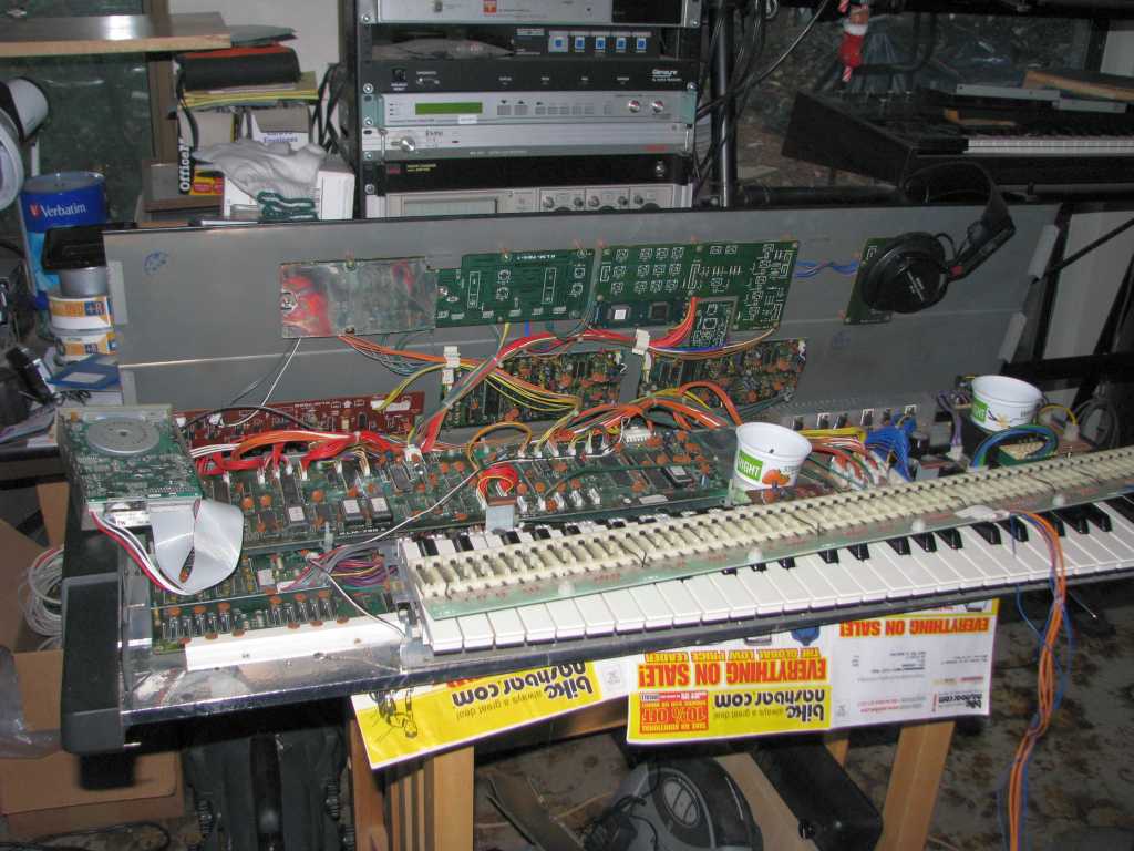
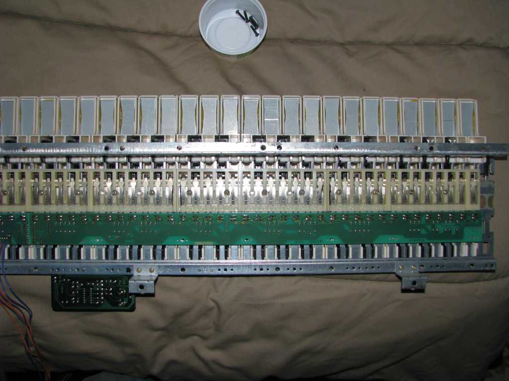
Disassembled. The long strip on top of the keyboard are the keyboard contacts. It's held on by about 30 small screws. Most of the mold and mess was on the top of the contact board, which meant that it had to be removed to be cleaned. 409 cleaner, clean paint brush, and compressed air to blow off the suds and water.
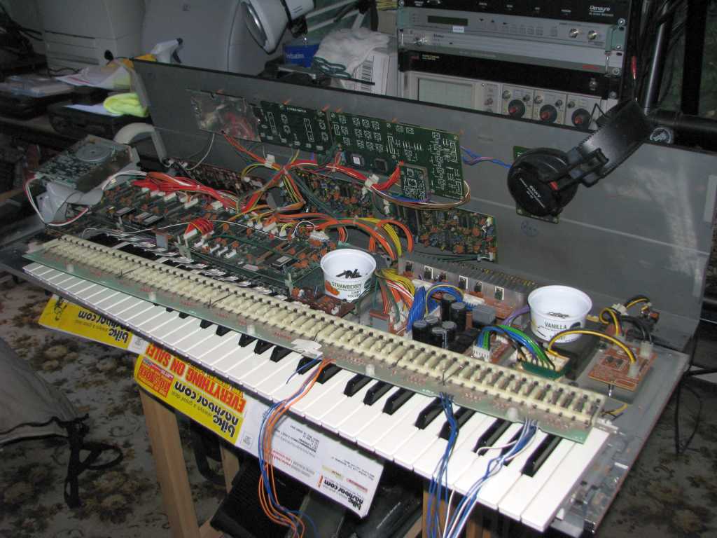
Same as before, but viewed from the right side. When removing the various keyboard connectors, you'll find that all of the connectors are identical and really easy to get mixed up. I used a colored marking pen to identify the plugs and corresponding jacks. Nail polish or wire labels would also have worked.
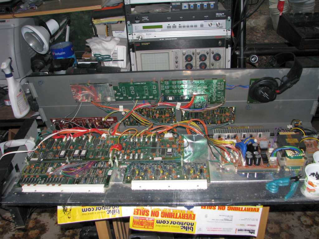
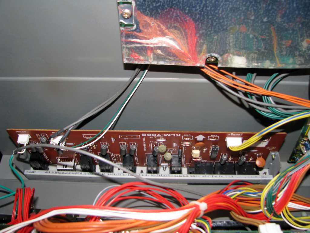
More, but with the keyboard removed.
by Jeff Liebermann AE6KS http://802.11junk.com
![]()